Electrical Schematics
Block Diagram

Team Color Circuit
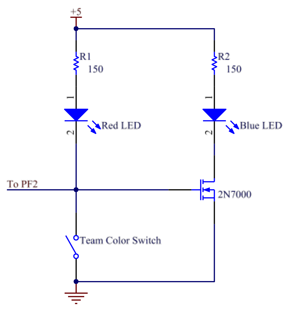
This circuit consists of a red LED and a blue LED, a 2N7000 nMOSFET, a switch and two protective resistors. The TIVA reads gate voltage of 2N7000 to check if we are assigned red team or blue team. When the switch is on, the red LED is turned on and the gate voltage is low, unable to switch on blue LED. When the switch is off, the gate voltage becomes high and the blue LED is turned on.
Game Status Circuit
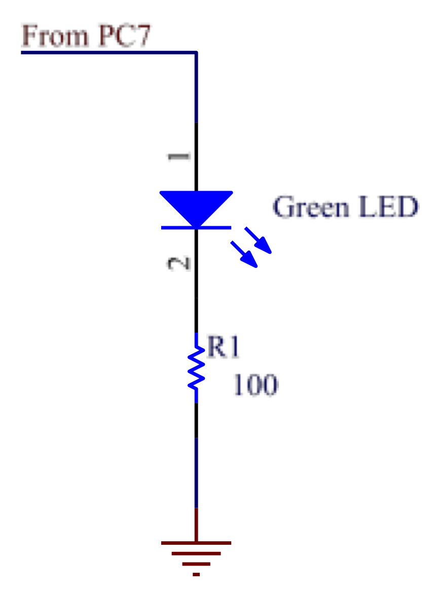
The game status LED circuit has two parts: one part consists of a switch and a protective resistor to inform the TIVA about game starting; the other part consists of a green LED and a protective resistor to receive TIVA output that lights up the LED when game is on.
Power Distribution Circuit
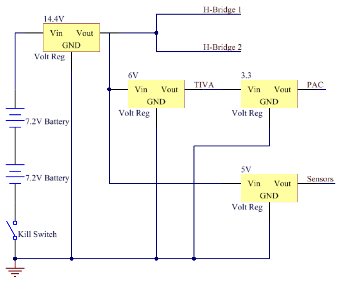
The power board consists of two 7.2-volt NiCd batteries, three voltage regulators and a kill switch. One voltage regulator is connected to the output of the two batteries and provides stablized 14.4V. Its output goes to motors and two other voltage regulators - one provides 6 volts to power TIVA and the other provides 5 volts for all sensor circuits. 10uF tantalum and 100uF electrolytic bypass capacitors were placed on the 5V and 6V lines. The kill switch controls the output of both batteries.
Motor Driver Circuit
The circuit has TLE 5206-2 as H-bridge, a DC motor and four capacitors for voltage stablization. One of these circuits was used for each of the two motors. The right motor used PB6 on IN1 for PWM and PB2 on IN2 for direction, and the left motor used PB7 on IN1 for PWM and PB1 on IN2 for direction using active-brake drive.
Magnetic Field Sensing Circuit
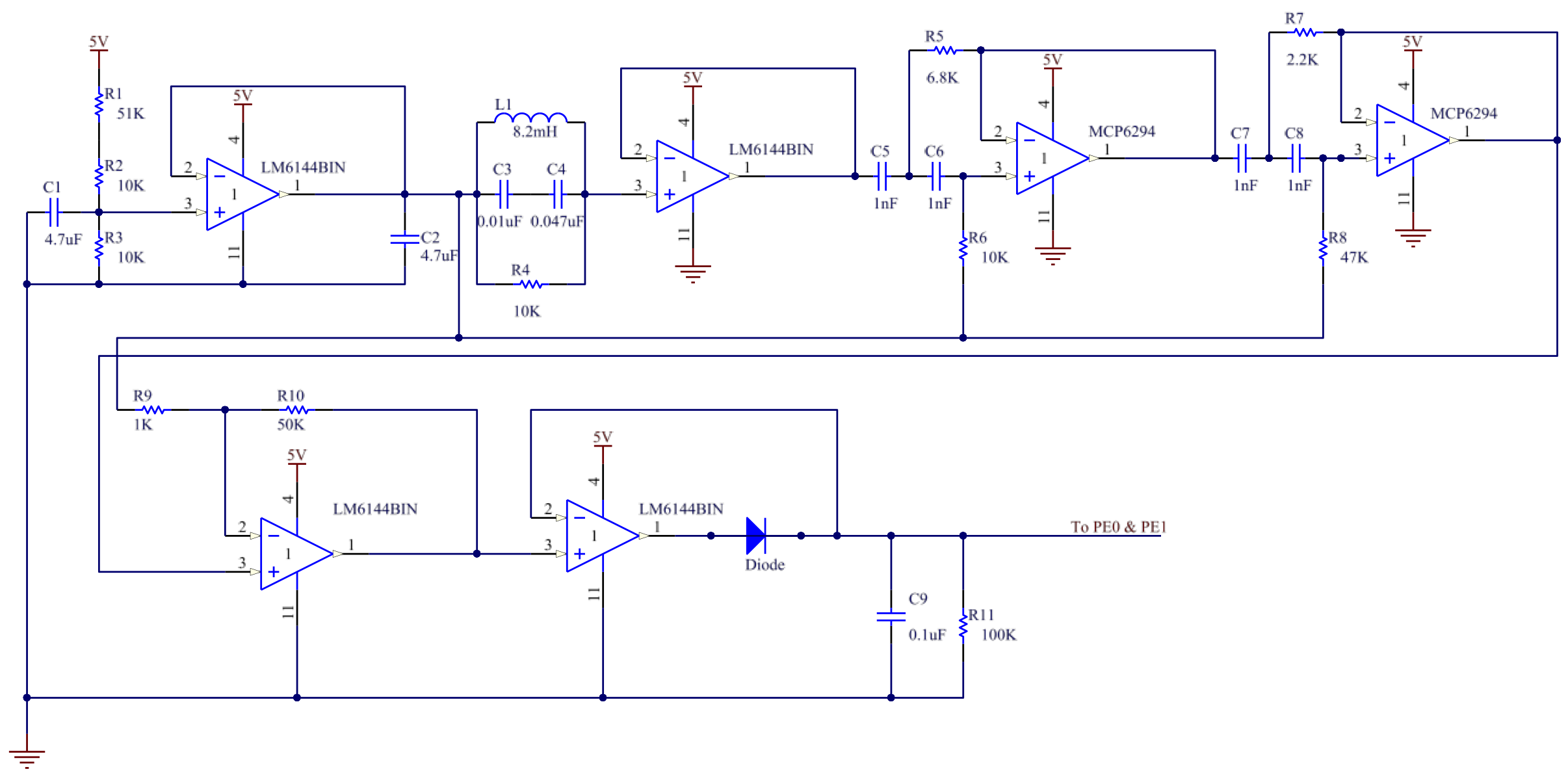
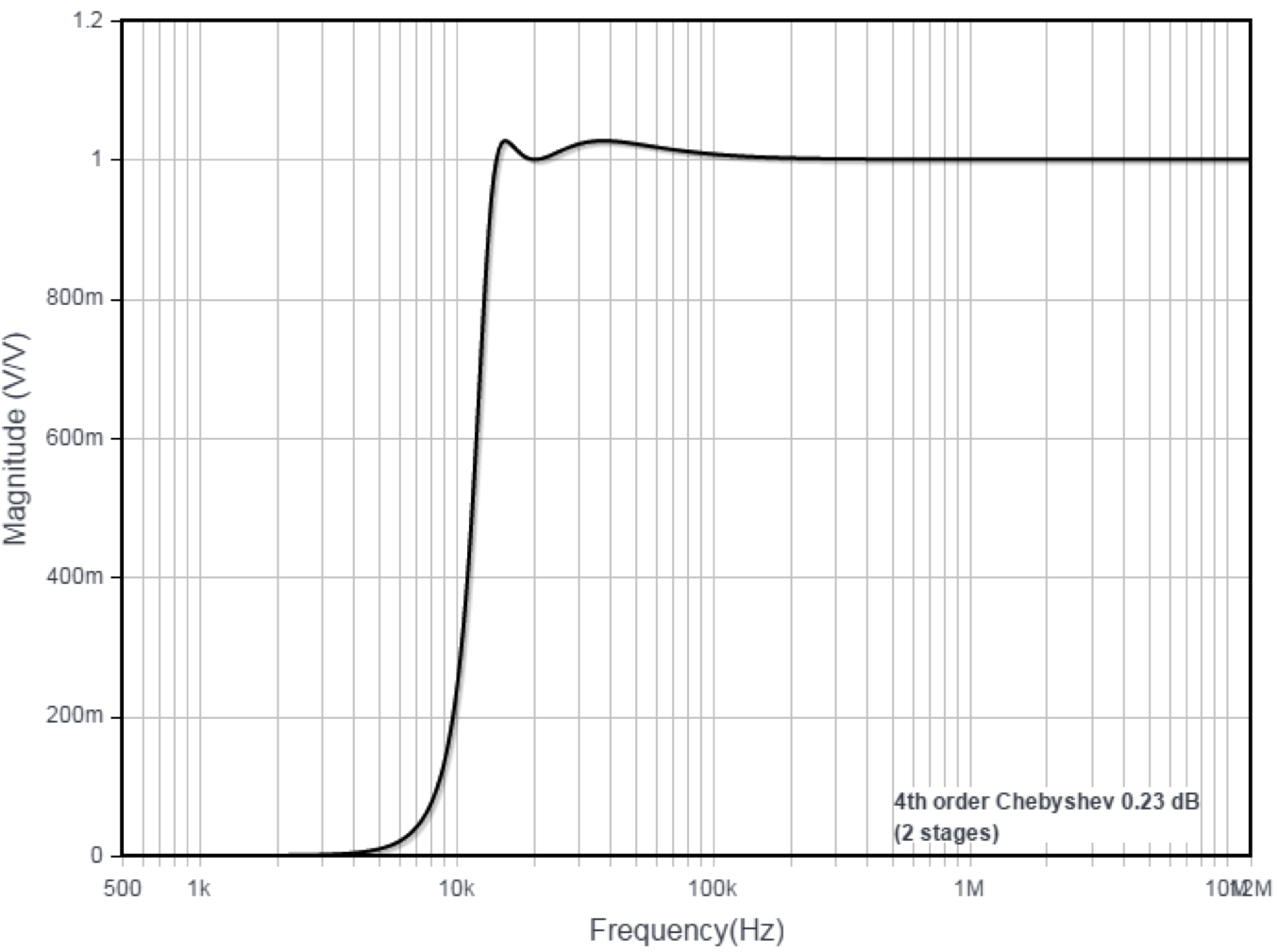
The magnetic field sensor circuit was used for converting the magnetic field signal from the 100mA (20kHz frequency) current to follow the campaign trail. An LCR circuit tuned to peak at 20kHz was built, and the signal was buffered and sent through a 4th order Chebyshev high pass filter (the transfer function is shown below) with a transfer response that cuts out frequencies below 5kHz completely (for all practical purposes). This was required to prevent the circuit from responding from the coil frequencies (and previous harmonics) at the polling stations. The high pass filtered output was then amplified in a low input current, quad, rail-to-rail (LM6144BIN) op amp. Then, the offsetted signal from the virtual groud was passed through a diode to remove negative going ripple and subsequently low-pass filtered to produce a proportional analog voltage. The high pass filter component was designed using the Analog Devices filter design wizard.
High pass filter transfer function [V/V].
Hall Effect Sensing Circuit
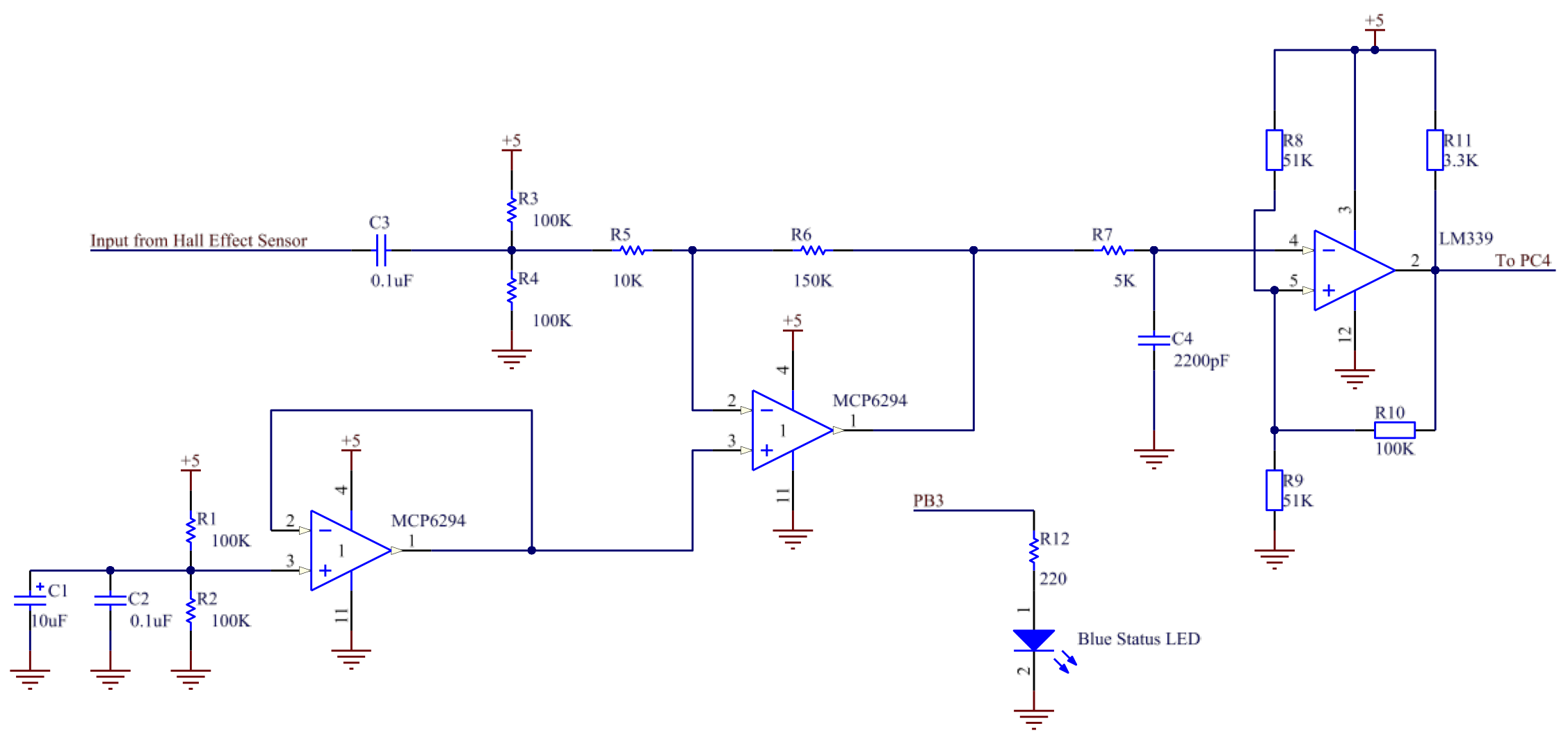
The hall effect sensor circuit consists of a hall effect sensor and amplification circuits powered by MCP6294 op-amp and a noise-filtering circuit powered by LM339 comparator. MCP6294 op-amp amplifies the signal 15 times and filters basic high-frequency noise with a 5K resisor and a 2200 pF capacitor. Then the LM339 comparator with hysteresis ignores wave ripples due to noise and produces a stable squared wave.
Servo Motors
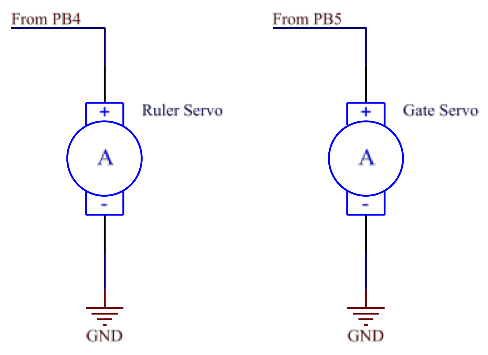
The servo motors have simple circuits with PWM lines from the TIVA. The most important thing was to drive them at the correct frequency (50Hz) to avoid overheating and draining the batteries.
Shooting Status Circuit
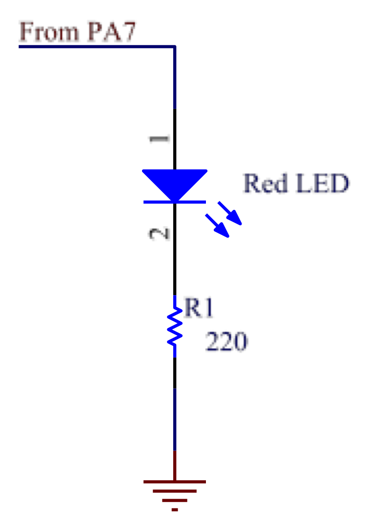
The status LED circuit has a yellow LED, a red LED and a green LED. These LEDs were used for testing purposes. In the actual testing, only red LED was used and it indicated whether the ball shooting mechanism worked well. The red LED will be on once the program enters shooting state machine and the servo presses down the ruler.
